The Journey to develop the Gillette order button
Introduction
In 2016, a creative team in Frankfurt had the idea of developing an IoT push button for ordering goods via a cellular module. In principle, something similar to the Amazon Dash button, except using a cellular radio instead of Wi-Fi. A first for the engineering team, and a tricky learning curve.
For data transmission, the developers selected a GSM module. Mobile communication on the GSM standard has the advantage of near universal coverage in all countries of Europe and many other countries in other continents. In 2016 no other wireless network offered such deep indoor coverage as the good, old and proven GSM standard, because NB-IoT did not exist at that time.
The developers in the IoT button team searched the internet for articles describing ways to build GSM antennas and to then design them into a product. They found, amongst other things, Harald Nauman’s IoT-M2M blog [1]. After registering for the blog and purchasing the IoT / M2M cookbook [2], the team received regular emails regarding new blog posts plus an update of the Cookbook.
PCB antennas
In the IoT / M2M Cookbook, the author describes in detail how to build your own GSM-PCB antenna. The design of the antenna is described in different variants. Taking this design the IoT button team found that the antenna design was so perfectly documented that it worked immediately in the IoT button prototype. At the same time, this self-built GSM antenna also fulfilled the requirement for an extremely low price point because it is based on a few conductor track segments. Being part of the layout of the printed circuit board, it does not add even one extra cent to the bill of materials and it saves the assembly costs for a surface mount antenna. No other design can beat the rock bottom price of 0.0 Dollars!
On the way to the mass production
In the phase following prototyping, IoT projects are often followed by the further optimisation of production costs, the reduction of the mechanical dimensions and the matching or tuning of the antenna. The IoT button also needed to go through this important process. In this phase, the work was given to an external engineering service company which had the necessary measuring equipment for measuring antennas. Unfortunately, the IoT button performance was badly degraded as a result. It was scaled down in size, the free antenna in the circuit board was exchanged for a cheap Flex-PCB antenna with poor specifications in order to fit the new enclosure. In this version, the IoT button, although smaller thanks to the Flex-PCB antenna, became more expensive to manufacture and no longer worked correctly.
Help from the akorIoT team
In the cases where a design is non-functional, there are problems with EMC radiation, interference from harmonic waves in the measurements of the RED (Radio Equipment Directive, formerly R&TTE -Radio and Telecommunication Terminal Equipment Directive) and other complex technical problems related to analogue design, many hardware developers ask for advice from the akorIoT team. Following their prototype success using the guidelines in the IoT / M2M cookbook, the developers of the IoT button also asked the author, Harald Naumann for advice.
Harald set up a meeting with an experienced RF developer: the Technical Manager of Triptec, Wilhelm Oelers, part of the akorIoT team. Together they visited the project manager of the IoT button. Over a cup of coffee, the modalities were clarified and after the measurement of the return loss of the antenna, the order to rework the printed circuit board was placed. The PCB antenna out of the IoT / M2M Cookbook went back in without increasing the PCB size. By replacing the Flex PCB antenna, the production costs were reduced again and the measurements after RED were successfully completed.
In addition, the antenna was optimized for Quad band GSM to NB-IoT (LTE-Cat NB1) in Band 8 and Band 20. With less effort, the IoT button can now quickly be redesigned to work over NB-IoT. Further methods to reduce costs were the use of two-layer PCBs and the removal of unnecessary components on the PCB.
Operation without battery change
The IoT push button has perfect power management. The retaining current with active timer and the push button is only 500 nA. The microcontroller switches everything off and waits patiently for the next button push or independently triggers the next order independently using an active timer.
During the GSM stress test, extreme operating conditions are tested. For this, a GSM tester simulates a GSM base station and asks for the maximum transmission power of 2 Watt (33 dBm) from the remote site. In the 2 Watt TX mode, the IoT button was able to send 520 orders on one set of three conventional Alkaline AA cells.
In actual use, the IoT button would be expected to place an order every two weeks. This equates to 26 orders for razor blades per year. This gives a theoretical expected useful life of 20 years for the worst case transmission scenario using a set of three AA batteries. However, in present GSM networks, the used TX power of IoT devices on GSM is generally much less than 33 dBm and so the batteries are capable of powering thousands of orders. Clearly, ageing and self-discharging of the AA cells are the limiting factors that will require the batteries to be replaced.
Malfunction source 1: design housing
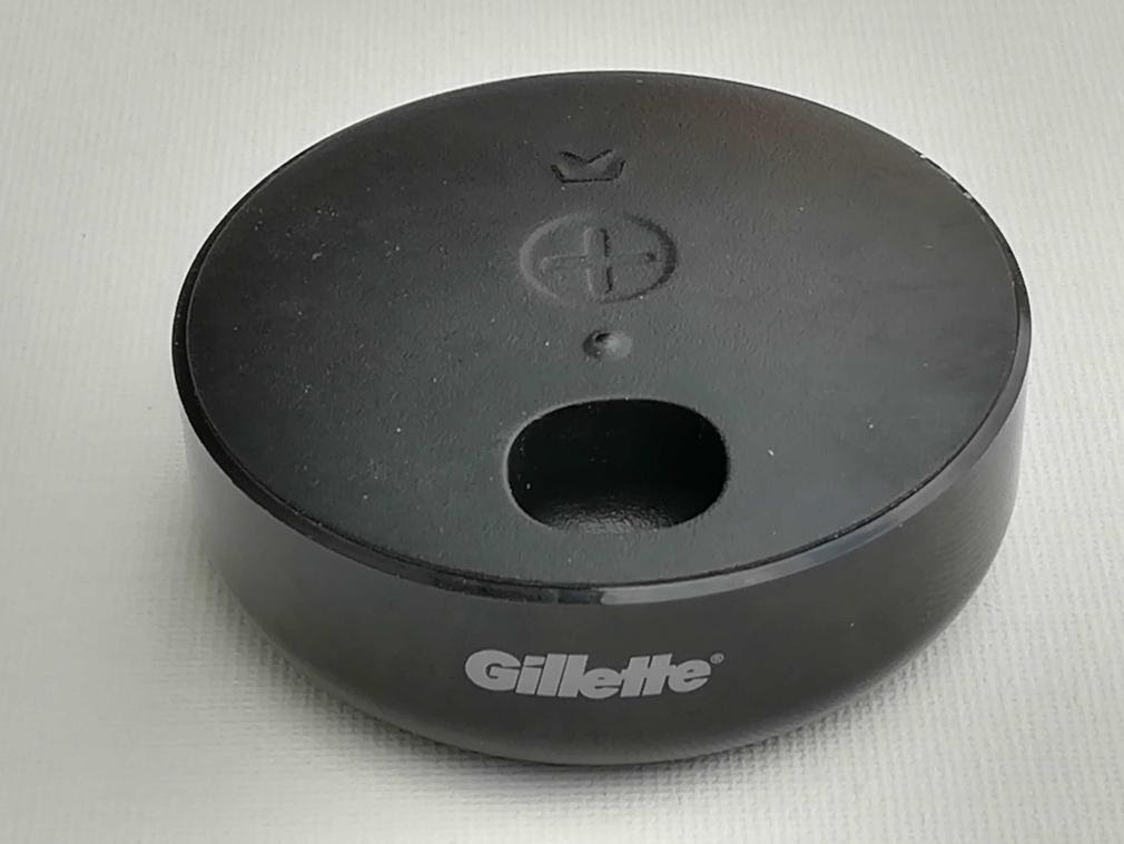
The electronics of the IoT button was now working perfectly and the cost was optimised. At this point, the designer suggested a new housing. The button is a lifestyle product, probably placed in plain sight in a customer’s bathroom and so needs a beautiful shape.
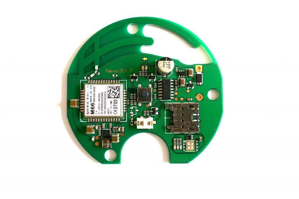
The circuit board of the IoT button by Gillette. It contains a GSM module, which can also be exchanged against a pin-compatible NB-IoT radio module.
Rectangular chip antennas do not fit into round corners. The GSM-PCB antenna does. It can be easily adapted to the new, round shape on the circuit board and can be optimised by practical test setups. Compared to this, a simulation is much more expensive and also time-consuming as for round structures the simulation software takes too long to run. In this phase of the project, copper foil and a craft knife are used and the cut foil is glued to the circuit board. Once the optimal structure is found, a new PCB can be ordered. This PCB is then measured again in the housing and the radiator is shortened by scratching or lengthened by soldering copper foil. Our two-layer PCB design for Gillette had such low spurious radiation in the measurement of the harmonic in the horizontal plane that our external test laboratory thought there was a malfunction with their measuring equipment.
If the designer then changes the material of the plastic for the housing, the thickness of the plastic or the material of the PCB, then the process must be repeated. The antennas must be adapted and optimised again. Details on this can be found in the IoT / M2M Cookbook [2]. It is important to have control over the manufacturing process so that “innocent” changes to the housing do not result in the mass manufacture of devices with de-tuned antennas!
Malfunction source 2: Purchase Department
Now the developers of an IoT device have nearly everything under control. The next hurdle is the Buyer. Buyers have the mission to lower production costs. If the buyer changes the supplier for the capacitors or inductances in the antenna-matching network in order to save costs, the antenna matching must be measured again. Each inductor behaves a bit like a capacitor and each capacitor behaves a bit like an inductor and this varies from manufacturer to manufacturer. If the buyer wishes to make a change to the components in the matching network, the new parts must have the same nominal values for both capacitance and inductance – and must be tested and matched once again.
Start of mass production
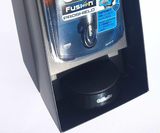
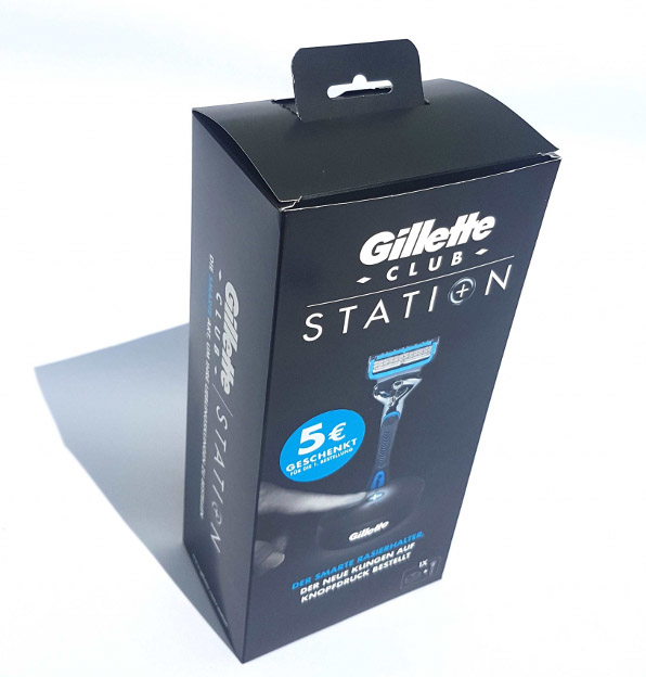
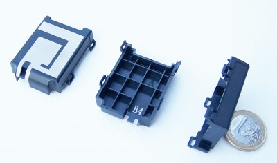
The final package design contains the razor (top) and the holder / IoT button for ordering razor blades (bottom).
With design and procurement complete, the IoT button was now ready and was successfully tested at Eurofins in Reichenwalde to the RED directive and can therefore carry the CE symbol.
The IoT button to order Gillette razor blades is produced by Nexolink Solutions AG based in Frankfurt. 22,000 Gillette order buttons have been produced. With its IoT button, Nexolink has developed a complete solution with a waterproof and stylish design for the ordering button plus all the software for the ordering processes that must run in the background.

0 Comments